Raising the Bar for N Scale Modular Railroading

Standards and Recommendations

Version 20230206

Overview

I like everything except…
When you decide to join an organization that already has adopted a set of rules or standards, you, by the fact of freely deciding to join, accept those rules. If you didn’t like those rules (standards), then continue your search for a group, any kind of group – model railroad, civic, religious, whatever – whose rules you agree with.

As Free-moN has grown lots of people have asked this question. We are open to change, but a standard that changes too easily or fast cannot be followed. Many groups are following this standard and it works. When there has been a real need to change, it has changed and will change if needed.

When the Standards do change it will not be done lightly. As a follower of the standard you agree to change with the standards as they change and grow.

When you decide to build modules to an existing standard, you, by freely deciding to adopt that particular standard, have accepted those standards as written. By choosing to adopt the Free-moN standard you have chosen to build modules that will connect with others building to this standard and will take design decisions that allow your module to connect to all others and to run trains across them, even those that use features of the standard that your particular module(s) may not.

Free-moN has a five member steering committee that is empowered to update the standard. When the Standards do change it will not be done lightly. The committee takes input from the Free-moN community (everyone building modules to the Free-moN standard) when considering a potential change and what changes to consider. As someone building to the Free-moN standard you agree to update your modules as the standards change and grow. Of course you always have the option to select a different standard that is better suited to your needs.

Objectives

How should I interpret the standards when one seems not to apply to the module I’m building? See last paragraph of Objectives
The goal of all modular railroad standards is to allow different people around the world to build modules and then get together, connect them with other modules, run trains across them and have fun. With this goal in mind, resolve conflicts by assuring that your module is not constructed in such a way that it prevents you from setting up with someone whose module makes use of a standard that does not seem to apply to your module.

Definitions

Is it important to distinguish between “modules” and “sections”? See “Definitions”

Yes! Modules consist of one or more sections. Each module must have at least 1 Free-moN compliant module end plate. There are restrictions to how and how many tracks may cross a module end plate. These restrictions assure that modules can connect to other modules and trains can operate smoothly when crossing between modules.

Sections allow modules to be taken apart into transportable pieces. Section ends (that are not module end plates) do not have the same restrictions as module end plates. This additional freedom is critical for building transportable modules that contain yards, continuous broad curves, industrial trackage, etc. The distinction between module ends and section ends makes Free-moN much more free.

Although the “Section ends” do not have to conform to the Free-moN standard in any way, it’s recommended that the construction standards be followed if possible. Using a thinner endplate or crossing closer to the edge could certainly lead to operational issues. Wiring between sections isn’t covered by the standard at all; some people continue to use APP connectors and some use other “Proprietary” means. As long as it’ll handle the current, whatever works is fine.

1.0 Framework

1.1 Endplates

1.2 Legs & Bracing

My module does not have grades, do I still need to have legs that can set my top of rail head height from 50 to 62 inches in ¾ inch increments? See S1.2.2 and S1.2.5.
No. If your module has legs that place the railhead at 50” off the floor and can accommodate a ±1” adjustment you meet the standard (S1.2.4). The standard does allow for grades up to a height of 62” in ¾” increments (S1.2.5). The intent of the increment interval is that ¾” or 1×” lumber can be used to raise modules. Show planners will provide the increment above 51” to get your module to the correct height should it be used in a part of the layout above 50”. If you do not want to have your module on blocks for height adjustment or you don’t have that much adjustment in your modules legs, please coordinate with the layout designer prior to the show so that your module can be setup at 50”.
The standard S1.2.2 says I need legs with +/- 1” adjustability, but it doesn’t say how to make them. What should I use for my legs?
That’s up to you! Some modelers use folding legs permanently attached to the module, others use detachable legs of a variety of types. Some common options are: 2x2 wooden leg sets with carriage bolt adjusters - EMT or plumbing pipe legs with a nut hammered/welded/otherwise fastened into the end for an adjustable foot - and extendable paint-poles threaded into a socket on the bottom of the module. If possible, look at some Free-moN (or even other scale Free-mo, it’ll be very similar) to get ideas before you decide on a method.

1.3 Surface

1.4 Fascia & Skirting

What’s the best way to set up my skirting S1.4.4?
One common way that a lot of modelers handle skirting, is to have black fabric about 43” long that can be clipped to the bottom of the fascia using binder clips or similar. Typically that fabric is not cut to size for a particular module; it’s left in full “Bolt” lengths (generally between 5 yards and 20 yards) and is run continuously along modules. Using this method, “your” skirting may be used on someone else’s modules and their skirting may be used on yours - but it’s much simpler to install a long continuous skirt than to deal with individual skirts on each module. To determine how much skirting you need, add up the lengths of both sides of your modules and be sure you have at least that much skirting. Keep in mind that fascia thickness can range from ⅛” all the way up to over ¾” so clips should accommodate that range.

2.0 Track

How far back from the end of the module do I stop my track?
Track ends flush with the end of the module. See section S2.7
What if my prototype uses double track spacing that is different from 1.125 inches (15 N-scale feet), can I build modules that use my prototype spacing? See S2.6.1.
Yes, within a module and across all section ends within a module you can use prototype (or other) double track spacing, provided that you return the spacing to 1.125 inches before crossing each module end plate.
Can I use #5 turnouts on my module? See S2.3
Yes, but not on the mainline. Industry tracks can use #5 turnouts.
Can I use curves smaller than 22 inch radius on my module? See S2.2
Yes, but not on the mainline. Industry tracks can use curves that are smaller than 22 inch radius. It is highly recommended to use curves larger than 15 inch radius, even for industrial tracks, to accommodate body mounted couplers.

It is “Recommended” to follow the standard, i.e. #6 turnouts and 22 inch radius, everywhere if possible. If it’s NECESSARY, smaller turnouts & sharper curves (and smaller code track, etc) can be used outside of the mainline but this should be avoided unless it either matches the prototype, or technical needs require it (e.g. size/space issues). Keep the objectives “To promote and require hi-fidelity prototypical scale model railroading” and “To ensure reliable track and electrical operation” in mind, on and off the mainline.

Can I use code 80 rail on my module? See S2.1
No. Code 80 rail should never be used on a Free-moN module.
Can I use Peco code 55 on my module? See S2.1
No. There are several reasons for this.

First, Peco code 55 track is actually code 80 rail buried part way into the ties.

Second, Peco, being a British company, builds track for British n-scale, which is 1:148 scale, but Free-moN is typically used for North American N-scale, which is 1:160 scale. Because of the scale difference, the tie spacing is wrong for North American track.

Finally, Peco track follows the NEM standards, but Free-moN requires rolling stock to meet NMRA standards (See S5.1). Because of this, the flangeways on Peco turnouts, and other special track, are too wide for NMRA standard wheelsets. Using Peco turnouts leads to increased derailments.

Do I need roadbed under all my track?
The mainline does need ⅛” thick roadbed per S2.5, which allows the module ends to line up properly - if one module had roadbed and another didn’t, then the scenic portion wouldn’t match up (since the railheads, of course, HAVE to line up). However, on your module if you want to have some track directly on the surface with no roadbed that’s fine. Remember there is a 2% maximum grade (S2.4), which means you should taper down from the ⅛” roadbed over at least 6-¼” to avoid having too steep of a grade.
The standard S2.1 specifies flextrack, or hand-laid track. I’m not experienced at laying track - why can’t I use sectional, or something like Kato Unitrack?
We want the module to be prototypical, and to have good operational characteristics. We feel this is not accomplished when using code 80 sectional or pre-made track. Unitrack, in particular, also wouldn’t fit the profile with other Free-moN modules because it uses Code 80 rail, and a 0.2” thick roadbed, where Free-moN requires Code 55 and a ⅛” (0.125”) thick roadbed (S2.1, S2.5). Talk to Free-moN builders about their methods for tracklaying, we’re glad to help out! Atlas code 55 sectional track can be used.

3.0 Wiring & Electrical

3.2 Turnouts

If I want to use DCC for turnout control, can I do that?
DCC controllable turnouts are fine, with a few caveats. First, you’d want to have the DCC turnout controller attached to the ACC bus, not the Track bus. This allows the turnout to be thrown, if a locomotive runs through it and causes a short - when the track bus is shorted, if turnout controls were on it they would not respond! Second, not all throttles are capable of controlling accessory decoders, so the turnout “Should” have a local control option as well - typically on the fascia. Third, because Accessory decoders have a fairly limited range of addresses, keep in mind that at a show someone else might be using the same addresses you are! So it may be necessary to reprogram during setup, or disable the DCC function during a show.
How should I control turnouts on my modules? The standard doesn’t say.
Turnout control is left to the builder, so you can choose whatever method you’d like. There are some considerations to keep in mind though:
  • Manual control (ground throws, slide switches) are simple, but it’s going to mean people are reaching into your scenery - there’s a potential for damage!
  • Fascia control is safer for your scenery, but keep in mind that modules don’t have a “public side” or “private side.” They can be controlled from either side, so if using fascia control it should be controllable from all sides.
  • DCC control is possible, but not all throttles support DCC accessory control (e.g. the Digitrax UT4 series). So, local control should also be provided.
  • Remember that frog power control is required by S3.2.1. Using your turnout control method to also switch polarity tends to be the easiest & cheapest solution, though there are also devices that will detect a loco and switch the frog automatically (Frog Juicer, AutoFrog, Frog-AR, etc).

3.3 Main Line Track Bus

Why doesn't the standard allow 14 AWG (American Wire Gauge) wire on the track and accessory buses? See S3.3.1 and S3.4.1

12 AWG specified in the standards may be overkill in some ways, but part of the reason it was selected in the first place was it can reduce the number of boosters needed on the layout without compromising the ability to detect shorts. Wire is still cheaper than another booster.

For the technical explanation, in order to reliably detect a short at the end of a booster district, the resistance of the wire needs to be kept low enough that we don't have a voltage drop of more than 0.5 volts at the end of the power district when we have a 5 amp short on the track (using the so called quarter test can induce this).

Using Ohms Law, this means the total resistance from the booster to the end of the district needs to be under 0.5 volts/5 amps = .1 ohm.

12 AWG wire has a resistance of .002 Ohms per foot and 14AWG wire has a resistance of .003 Ohms per foot. For 14 AWG wire, the maximum distances is .1 ohm/ .003 ohm/foot = 33.33 feet. For 12 AWG wire, the maximum distance is .1 ohm/.002 ohm/foot = 50 feet. This means a single booster placed in the center of a district can safely power up to 100 feet of track with 12 gauge wire, but only 66.66 feet of track using 14 gauge wire. In practice, we try to make our booster districts slightly smaller than the maximum limits to accommodate other sources of resistance (connectors, feeder wire, etc) in the circuit.

On a large layout, this difference can significantly increase the cost of powering the layout. For example, if we have 1000 feet of track using 12 AWG wire for the bus, we need a minimum of 10 boosters to adequately power the track. With 14 AWG wire for the bus, we need a minimum of 15 boosters to safely power the same amount of track.

I tried to follow the standard for my track bus, but when I plug my modules together - a red wire is going to a black wire. What did I do wrong?
The standard for track bus connectors is always confusing to new builders. The thing to remember, is that Free-moN modules can connect in ANY direction. So if you’re using Red and Black wire for your Track Bus, that lets you keep straight on that module which color goes to which rail. But that color might have the opposite meaning on the next module, depending on what direction it’s facing! S3.3.3 / S3.3.4 state that the Anderson PowerPole connectors should be stacked hood-up, tongue-down - and that the top connector should fasten to the left rail, as you’re facing the end of the module. If you are using red/black, that means that the Red wire will be on top at one end, and the Black on top at the other end. Since the Left rail is the Top connector on your module, if you turn around and look at the module it’s connecting to - the top connector on THAT module is also the left rail. But that’s just as you’re facing each of them! Once they’re plugged together, the appropriate rails WILL connect to one another - the color isn’t relevant, it’s the orientation that matters.

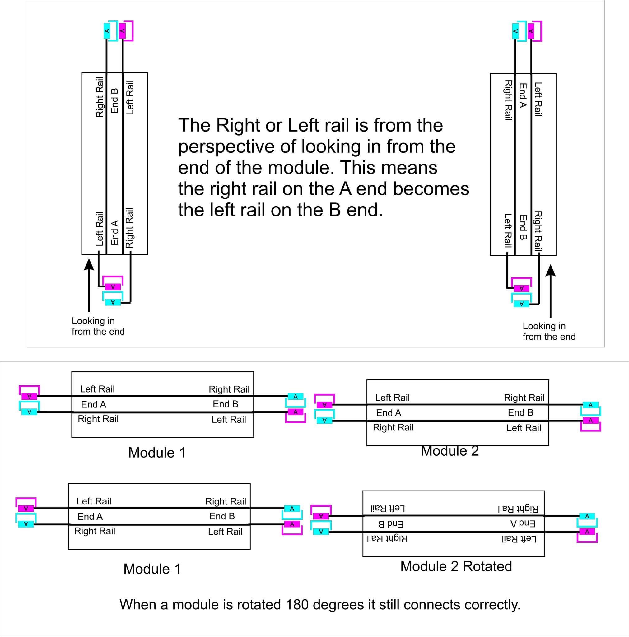
The following drawing, provided by Bob Schrempp provides a nice graphical explanation of the connectors.

PowerPole wiring example from Bob Schremp

3.4 Accessory Power Bus

I don’t have any accessories on my module. Do I need to install an ACC bus?
Yes, per S3.4.1 the ACC bus is required even if it’s not used on the module. It will be used to ensure a continuous ACC bus from the booster or AC adapter, so even if your module isn’t using it - the next one in line might be, so we need your ACC bus to get ACC power to it.
I’m confused by the ACC bus. Per RP3.4.2.2 It could be DCC, or it could be 16VAC? How do I use it to power something, if I don’t know what the voltage will be?
The good news is, that DCC is essentially a form of AC current. So if you just need “Power,” you can rectify the ACC bus to DC and use a voltage regulator to get a consistent DC voltage output, over a range of AC voltage inputs. There are “AC to DC Step Down Buck Converters” available from a variety of sources that typically will work on a wide range of AC input voltage and provide a fixed DC output voltage. Depending on the current you need, one or more of these on your module would handle either type of input.
Why are 30-amp Anderson PowerPole connectors required S3.3.3? I thought that the DCC booster only put out around 5 amps?
The Anderson PowerPole connector will actually accommodate three different sizes of terminal - 15A, 30A, and 45. The reason we’re using the 30A is that it’s the one sized for 12ga-14ga wire. The 45A is for 10ga and larger, and the 15A is for 16ga and smaller wire. So the 30A is used because it fits the wire size used in our buses, not because we need 30A of capacity.

3.5 LocoNet Bus

How many throttle jacks do I need on the sides of my module for connecting wired throttles? See S3.5.1
Two, one on each side of the module. Note a module consisting of multiple sections is still only required to have 2, one phone jack somewhere on each side of the entire collection of sections. These 2 jacks need not be on the same section. Thus, for example, a 50 foot module is still only required to have 2 jacks for connecting wired throttles. Owners of large modules (e.g., the 50’ mentioned above) are asked to consider if operators are likely to congregate along that module and then provide sufficient jacks. For example, a 50’ module of scenery with a single track or a passing siding would likely be fine with 1 jack per side. However, a 50’ yard module could have numerous operators looking for a jack. Consider placing additional jacks where the operators are likely to need them. One jack at one end of the 50’ yard module meets the standard, but would not be useful for operator(s) with a plugin throttle switching at the opposite end of the 50’ yard module.
The standard S3.5.1 specifies a LocoNet bus, but I’m using NCE/EasyDCC/MRC/Lenz/etc. brand DCC at home. Do I still need to support LocoNet?
The LocoNet throttle bus is generally used at shows, where Digitrax hardware is the most common method for controlling the layout. You can use a different brand of DCC at home, but the module does still need a LocoNet-compatible throttle bus, and if the module is 48” or longer it needs an RJ12 throttle jack on each side. The RJ12 jack must support Digitrax, but some other manufacturers can use RJ12 as well. For example, NCE throttle panels will also support Digitrax throttles when connected to LocoNet - but Digitrax throttle panels will not support NCE.
The Standard says I have to have throttle panels on my module if it is 48 inches long or longer, but I don't use wired throttles at home, do I have to mount throttle panels in the module's fascia? See S3.5.1
No. The standard doesn't say that throttle panels provided on modules must be in a fixed location, so it is perfectly acceptable for a module owner to provide clip or clamp on throttle panels.
What type of wire should I use for my throttle network cables?
The standards don't specify which type of cable you use, but the preferred cable is flat 6 conductor data cable, sometimes referred to as satin silver cable. Do not use CAT5 or CAT6 Ethernet cables for your throttle network, as the twisting in these cables can cause communication issues with the protocols used for DCC systems.

4.0 Scenery

Can I run a road or a river to the endplate?
No, the scenery at the end plate needs to flat and level. Most roads don’t end in a deadend. Please veer all road to the sides of the module to avoid the end plate.

5.0 Equipment

I built (or ran on) a Free-moN module, but my loco and/or car is “Chattering” as it rolls along the track. What’s going on?
Modern scale equipment tends to come with low profile wheel flanges, but older N scale designs used deep-flanged wheels. We refer to them as “Pizza Cutters.” Those deep flanges will hit tie tie plates on Code 55 track, causing that noise. For cars, swapping wheels is pretty straightforward - you can get “low profile” wheels from a variety of sources (Micro-Trains, Fox Valley, etc). If a locomotive has deep-flange wheels, that’s harder to fix. There are options, talk to a Free-moN builder about it - but sometimes, the simplest solution is to not use that loco on Free-moN.

6.0 Miscellaneous

6.1 Crowd Control Barrier System